Reinstalling the Front Scanner Wire
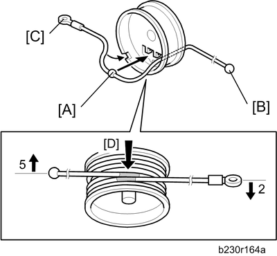
Position the center ball [A] in the middle of the forked holder.
Pass the right end (with the ball) [B] through the square hole. Pass the left end (with the ring) [C] through the notch.
Wind the right end counterclockwise (shown from the machine’s front) five times. Wind the left end clockwise twice.

The two red marks [D] come together when you have done this. Stick the wire to the pulley with tape. This lets you easily handle the assembly at the time of installation.
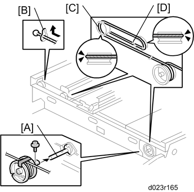
Install the drive pulley on the shaft [A].
Do not attach the pulley to the shaft with the screw at this time.
Insert the left end into the slit [B]. The end should go via the rear track of the left pulley [C] and the rear track of the movable pulley [D].
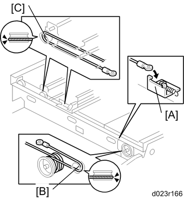
Hook the right end onto the front scanner wire bracket [A]. The end should go via the front track of the right pulley [B] and the front track of the movable pulley [C].
Do not attach the scanner wire bracket with the screw at this time.
Remove the tape from the drive pulley.
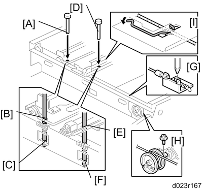
Insert a scanner-positioning pin [A] through the 2nd carriage hole [B] and the left holes [C] in the front rail. Insert another scanner positioning pin [D] through the 1st carriage hole [E] and the right holes in the front rail [F].
Insert two more scanner positioning pins through the holes in the rear rail.
Screw the drive pulley to the shaft [G].
Screw the scanner wire bracket to the front rail [H].
Install the scanner wire clamp [I].
Pull out the positioning pins.
Make sure the 1st and 2nd carriages move smoothly after you remove the positioning pins. Do steps 8 through 13 again if they do not.