Toner Pump Unit
There are four pump units inside the machine. This procedure describes the replacement procedure only for one unit. If you need to replace another unit, do the same as this procedure.
![]()
Put some sheets of paper on the floor before doing this procedure. Toner may fall on the floor.
Rear cover (
 Rear Cover
 )
)Image transfer belt unit (
Image Transfer Belt Unit)All PCDUs (
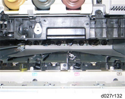
PCDU) Put a sheet of paper (A3/DLT) inside the machine as shown and on the floor.

The sheet of paper on the floor is used in a later step.
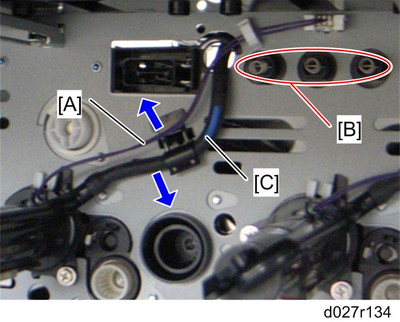
Release the harness [A] from the clamp (
 x 1 for YCM, x 2 for K) and hook, and then disconnect the harness.
Avoid touching these spring terminals [B].
Release the toner supply tube [C].
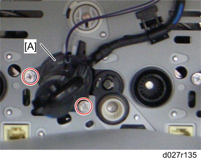
Remove the toner pump unit [A] (
 x 2)
x 2)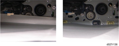
Make sure that a sheet of paper is attached to the frame of the rear side. The picture on the left shows a sheet of paper that is correctly set, but the picture on the right shows a sheet of paper that is not correctly set. This sheet of paper prevents toner and screws from falling into the laser optics housing unit through cutouts.
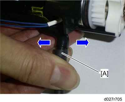
Slowly remove the toner supply tube [A] from the toner pump unit by pulling the tube right and left.
Turn up the openings of the toner pump unit and toner supply tube just after removing the tube.
If not, the toner may scatter away and fall down.
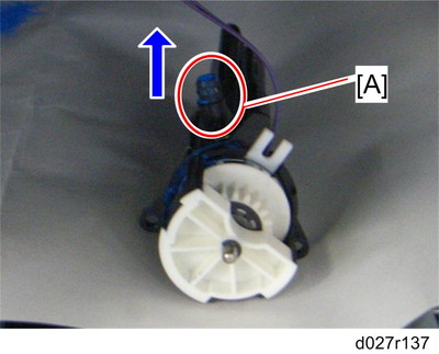
Put the toner pump unit on the sheet of paper, which has been put in step 4, with its opening [A] up.
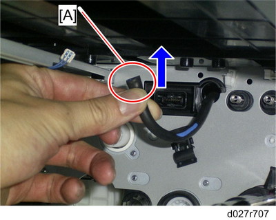
Keep the opening [A] of the toner supply tube up, and then clip the opening of the toner supply.