Installation Procedure
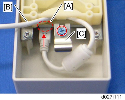
Connect the USB cable [B] to the USB slot [A] in the USB2.0/SD Slot as shown above.
Attach the ground plate [C] to the bracket of the USB2.0/SD Slot (
 x 1: M3x6 blue).
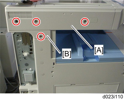
Rear cover of the machine (
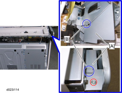
x 8)Remove the scanner left cover [A] (
x 2).Remove the left frame cover [B] (
x 1).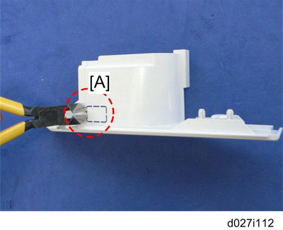
Remove the part [A] of the left frame cover with pliers or a similar tool.
Reinstall the left frame cover (
x 1).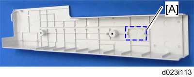
Remove the part [A] on the scanner left cover.
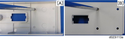
Make four holes in the scanner left cover with a screwdriver as shown [A].

Smooth the four holes in the scanner left cover as shown [B].
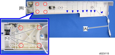
Route the USB cable [A] through the gaps in the left scanner cover.
Secure the USB2.0/SD Slot [B] with the left scanner cover as shown above (
x 4: M3x8).Use the screw holes [C] as shown above.
Attach the bracket [A] with its two hooks [B] as shown above (
x 1: M3x6).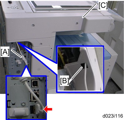
Put the USB cable [A] through the cutout [B] of the left frame cover.
Attach the scanner left cover [C] to the mainframe, and then connect the USB cable [A] to USB-A (front side) as shown above.
Make sure that the USB cable is inserted in USB-A (front side).
Reinstall the rear cover (
x 8).If PostScript 3 is already installed, go to step 25. If not, follow the steps from 16 to 24.
Remove the SD slot cover (
x 1), and move the SD card from slot 1 to slot 2.Insert the PDF direct card in slot 1.
Plug in and turn on the mainframe.
Enter the System SP mode.
Move HDD Security Applications (HDD Encryption unit and Data Overwrite Security Unit) from the SD card in slot 2 to the SD card in slot 1 with SP5-873-001 "Move Exec".
Enter the Scanner SP mode, and then change the setting of SP1013-001 from “0” to “1”.
Enter the Printer SP mode, and then change the setting of SP1110-001 from “0” to “1”.
Exit the SP mode, and then turn off the machine.
Remove the SD card in slot 2, and then attach the SD slot cover (
x 1).Keep this card in the safe place (
 SD Card Appli Move
 ).
).
Check the operation of the USB2.0/SD Slot.
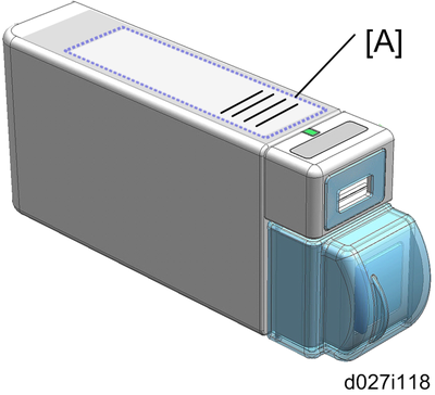
Attach the decal [A] to the USB2.0/SD Slot as shown above.