Gear Unit
All PCU's
Image transfer belt unit (
 Image Transfer Belt Unit
 )
)Rear cover (
Rear Cover)Controller box (
Controller Box)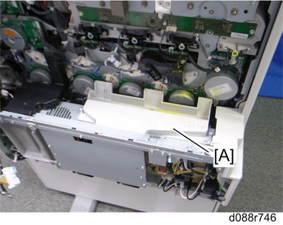
Toner sump cover [A] (hooks)
Third duct (
Third Duct Fan)Left cover (
Left Cover)PSU bracket (
PSU)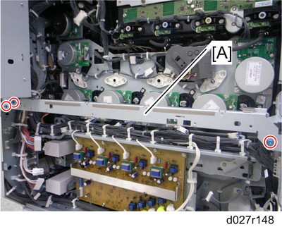
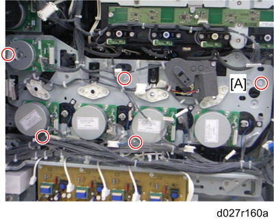
Remove the rear stay [A] (
 x 3).
x 3).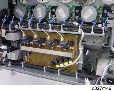
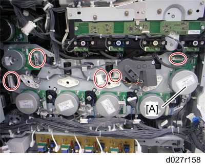
Remove ten clamps (blue arrows).
Release seven clamps and turn each harness aside.
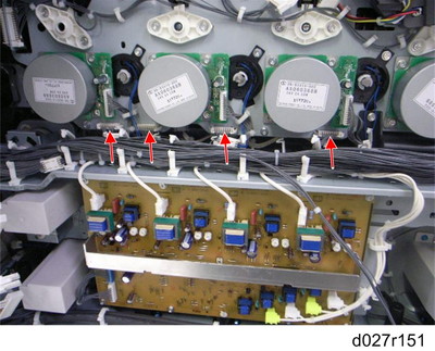
Disconnect four connectors (red arrows).
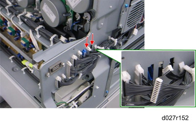
Disconnect two connectors (red arrows) and put these harnesses inside the machine.
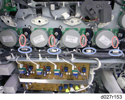
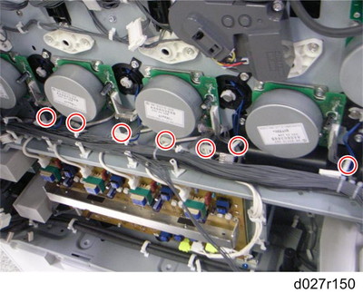
Disconnect each connector (red circles) from the drum/development drive motors (
 x 1,
x 1,  x 1 each).
Disconnect each connector (blue circles) from the development clutches (
x 1 each).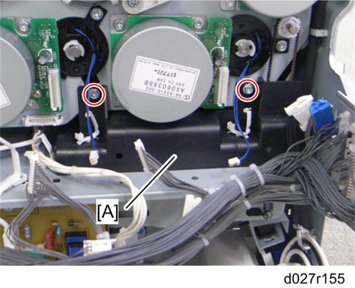
Cover [A] (
x 2)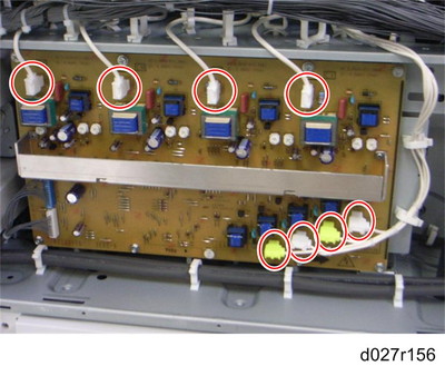
Disconnect eight connectors from the high voltage supply board (
x 8, x 2).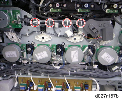
Release four clamps (red circles) and turn the harnesses aside.
Disconnect five connectors (red circles) (
x 5).Toner transport motor [A] (
x 3)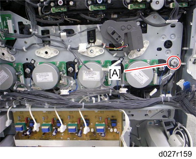
Pulley [A] (timing belt)
Gear unit [A] (
x 8)