Switching ON and Setting UP Save Debug Log
The debug information cannot be saved until the “Save Debug Log” function has been switched on and a target has been selected.
Enter the SP mode and switch the Save Debug Log feature on.
Enter the SP mode.
Touch “System SP”.
On the LCD panel, open SP5857.
Under “5857 Save Debug Log”, touch “1 On/Off”.
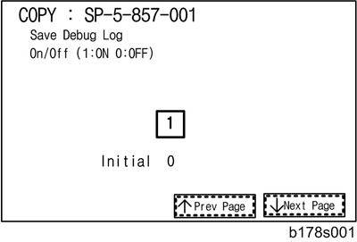
On the control panel keypad, press “1”. Then press
 . This switches the Save Debug Log feature on.
The default setting is “0” (OFF). This feature must be switched on in order for the debug information to be saved.
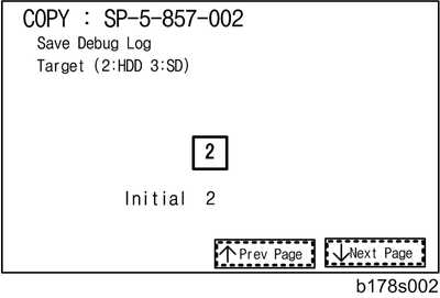
Select the target destination where the debug information will be saved. Under “5857 Save Debug Log”, touch “2 Target”, enter “2” with the operation panel key to select the hard disk as the target destination. Then press
.Select “3 SD Card” to save the debug information directly to the SD card if it is inserted in the service slot.
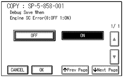
Now touch “5858” and specify the events that you want to record in the debug log. SP5858 (Debug Save When) provides the following items for selection.
1
Engine SC Error
Saves data when an engine-related SC code is generated.
2
Controller SC Error
Saves debug data when a controller-related SC Code is generated.
3
Any SC Error
Saves data only for the SC code that you specify by entering code number.
4
Jam
Saves data for jams.
More than one event can be selected.
Example 1: To Select Items 1, 2, 4
Touch the appropriate items(s). Press “ON” for each selection. This example shows “Engine SC Error” selected.
Example 2: To Specify an SC Code
Touch “3 Any SC Error”, enter the 3-digit SC code number with the control panel number keys. Then press
. This example shows an entry for SC670.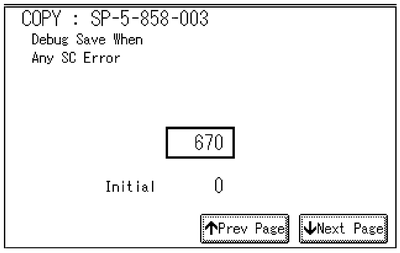
For details about SC code numbers, please refer to the SC tables in Section 4. “Troubleshooting”.
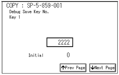
Select one or more memory modules for reading and recording debug information. Touch “5859”.
Under “5859” press the necessary key item for the module that you want to record.
Enter the appropriate 4-digit number. Then press
. Refer to the two tables below for the 4-digit numbers to enter for each key.
The example below shows “Key 1” with “2222” entered.
The following keys can be set with the corresponding numbers. (The initials in parentheses indicate the names of the modules.)
4-Digit Entries for Keys 1 to 10 Key No.
Copy
Printer
Scanner
Web
1
2222 (SCS)
2
14000 (SRM)
3
256 (IMH)
4
1000 (ECS)
5
1025 (MCS)
6
4848 (COPY)
4400 (GPS)
5375 (Scan)
5682 (NFA)
7
2224 (BICU)
4500 (PDL)
5682 (NFA)
6600 (WebDB)
8
4600 (GPS-PM)
3000 (UCS)
3300 (PTS)
9
2000 (NCS)
2000 (NCS)
6666 (WebSys)
10
2224 (BICU)
4126 (DCS)
2000 (NCS)
The default settings for Keys 1 to 10 are all zero (“0”).
Key to Acronyms Acronym
Meaning
Acronym
Meaning
ECS
Engine Control Service
NFA
Net File Application
GPS
GW Print Service
PDL
Printer Design Language
GSP-PM
GW Print Service – Print Module
PTS
Print Server
IMH
Image Memory Handler
SCS
System Control Service
MCS
Memory Control Service
SRM
System Resource Management
NCS
Network Control Service
WebDB
Web Document Box (Document Server)
The machine is now set to record the debugging information automatically on the HDD (the target selected with SP5857-002) for the events that you selected with SP5858 and the memory modules selected with SP5859.
Please keep the following important points in mind when you do this setting:
Note that the number entries for Keys 1 to 5 are the same for the Copy, Printer, Scanner, and Web memory modules.
The initial settings are all zero.
These settings remain in effect until you change them. Be sure to check all the settings, especially the settings for Keys 6 to 10. To switch off a key setting, enter a zero for that key.
You can select any number of keys from 1 to 10 (or all) by entering the corresponding 4-digit numbers from the table.
You cannot mix settings for the groups (COPY, PRINTER, etc.) for 006 to 010. For example, if you want to create a PRINTER debug log you must select the settings from the 9 available selections for the “PRINTER” column only.
One area of the disk is reserved to store the debug log. The size of this area is limited to 4 MB.