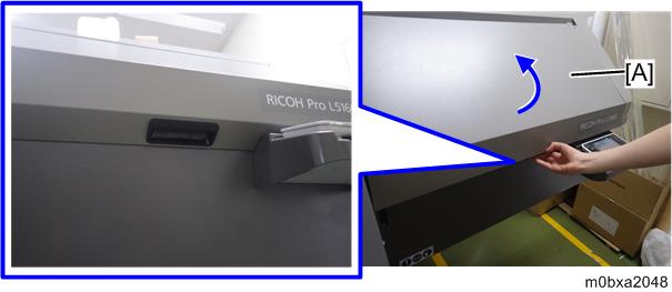
Open the right front cover [A].

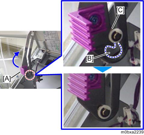
Lift the lock lever [A] tightly to let the shaft [C] fit the cutout section [B] of the bracket.
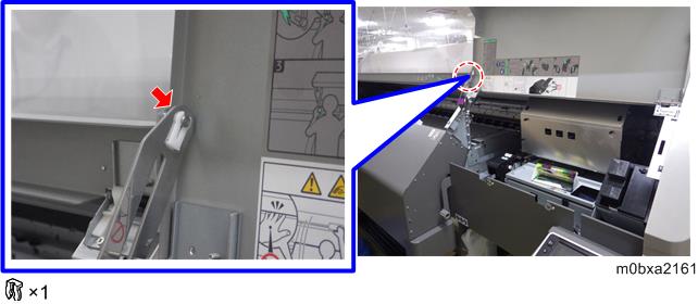
- Remove the clip of the right front cover.
- Close the right front cover.
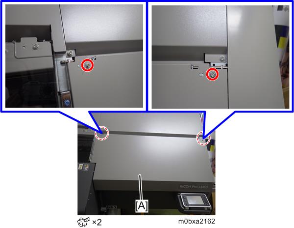
- Remove the right front cover [A].
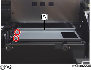
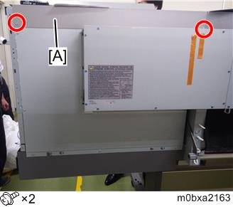
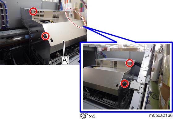
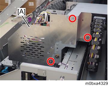
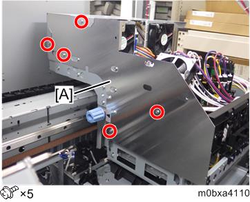
- Remove the right upper cover [A].
- Front side, Upper side
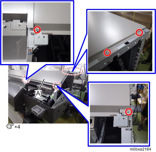
- Rear side
- Front side, Upper side
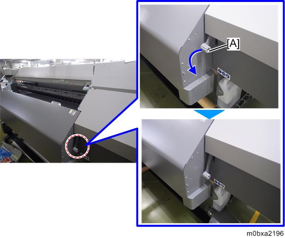
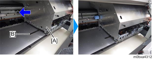
- Turn the handle [A] to lower the cap unit [B].
(Change the state of decap)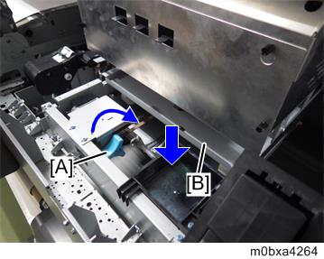
- Move away the carriage [A] to the center of the main machine.
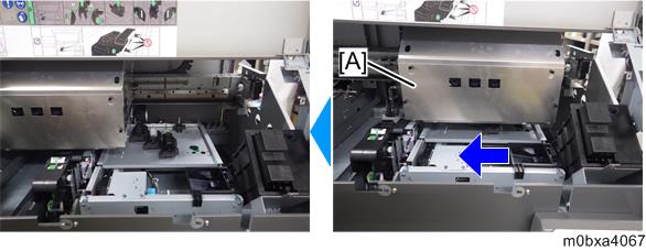
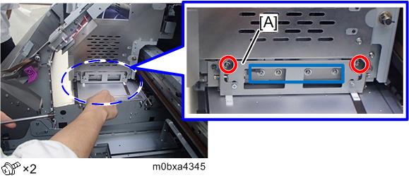
- Remove the carriage front lower cover [A].
When removing the carriage front cover, loosen the screws [B].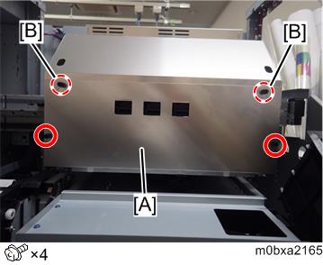
- Remove the carriage front cover [A].
- Remove the carriage covers [A] at the left and right side.
- Right side
- Left side
- Right side
- Loosen the two screws, and then move the left and right jam detection feelers to the highest position.
- If the media holding lever is raised, lower it.
- Measure the distance between the platen and the surface of each head nozzle at the three points of the platen (right edge, middle, left edge) by the gap gauge to make sure that they are within the extent of 1.8 ± 0.2 mm (approx. 0.071 ± 0.008 inch).
- Put the gap gauge (1.8 mm (approx. 0.071 inch)) [A] on the platen.
- Move the carriage to the center of the platen to pass the carriage above the gap gauge.
- Check if the gap gauge is out of position.
- Place the gap gauge (1.9 mm (approx. 0.075 inch)), and slide the carriage. Make sure that the gauge is shifted from the original position.
- Put the gap gauge (1.8 mm (approx. 0.071 inch)) [A] on the platen.
- If the value is not within the extent of the reference value (1.8±0.2 mm (approx. 0.071 ± 0.008 inch)), perform Print Head Height Adjustment.
- Attach the left and right jam detection feelers.
- Attach the left and right carriage covers.
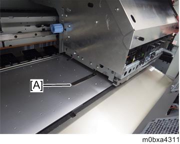
- Reattach the ink receiving port upper cover [A].