
The colorimetric sensor cannot detect the head position of the white ink head (Head 2).
Check the printed image to determine the head position, and then adjust it.
It is recommended that you adjust Head 1 and Head 3 using the colorimetric sensor and manually adjust Head 2 only.
The media must be changed according to the target head during adjustment.
Head Inclination Adjustment
- Make sure the following conditions are met.
- Make the machine ready to print.
- Use a media on which the dots will not be blurred, for example glossy paper or PVC. For white ink adjustment, use PET (media that enables you to see the white ink, such as transparent media).
- The media width must be 420 mm or wider.
- Execute head cleaning. (About Head Cleaning)
- Print the nozzle check pattern to make sure there are no defects in heads 1-3. (Nozzle Check Pattern Printing/Checking)
- Execute SP5-922-004 from the operation panel.
- After the execution is completed, check the printed image and adjust the head inclination according to "Measuring Head Inclination (Absolute) (Adjustment after Replacing the Print Head Unit)". Because the amount of inclination is not displayed, determine the amount of adjustment by looking at the image.
- The printed image
The following image is printed for each head.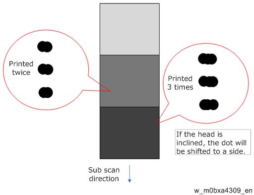
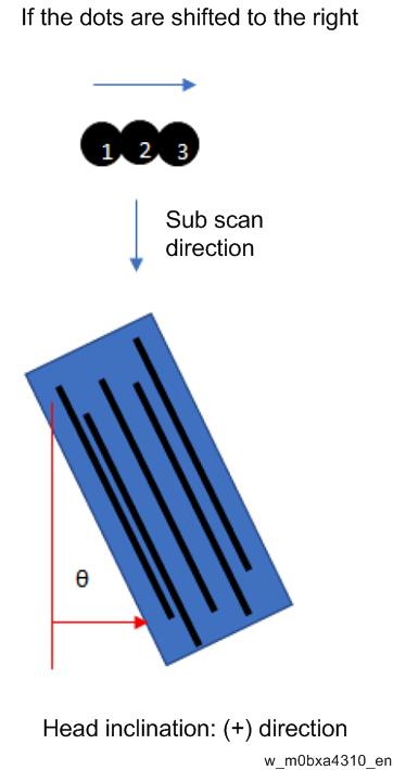
- Directions of dot shifting and head inclination
In the figure above, the lightest patch is printed once, the center patch is printed twice, and the darkest patch is printed three times. Check all patches in order and determine in which direction the dots are shifted.
- The printed image
- Repeat steps 2 - 5 until the dots printed by the target head are aligned.
Allowable range of head inclination is follows: the part [A] is 20 m or less.
Actual dot photograph (3 dots overlap) in case of 15m head inclination.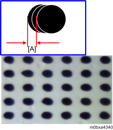
Sub Scan Direction Head Position Adjustment
- Make sure the following conditions are met.
- Make the machine ready to print.
- Use a media on which the dots will not be blurred, for example coated paper, glossy paper or PVC. For white ink adjustment, use PET (media that enables you to see the white ink, such as transparent media).
- The media width must be 420 mm or wider.
- Execute head cleaning. (About Head Cleaning)
- Print the nozzle check pattern to make sure there are no defects in heads 1-3. (Nozzle Check Pattern Printing/Checking)
- Execute SP5-922-005 from the operation panel.
- After the execution is completed, check the printed image and adjust the head position according to "Measuring Head Inclination (Measuring Sub Scan Deviation) (Adjustment after Replacing the Print Head Unit)". Because the amount of inclination is not displayed, determine the amount of adjustment by looking at the image.
- Printed image
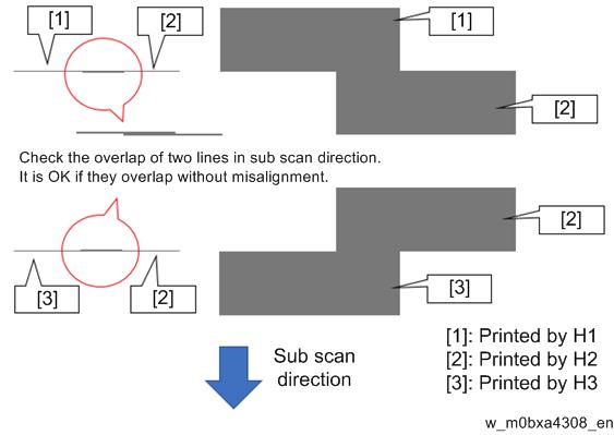
- If the line printed by H2 is shifted to the (+) side in the sub scan direction, move H2 in the (+) direction using the cam.
- The amount of line misalignment cannot be confirmed with the unaided eye. Use a magnifier or a similar tool to magnify the printed image.
- First align Heads 1 and 2, and then Heads 2 and 3.
- Adjustment is complete when there are no misalignment between Heads 1 and 2 and between Heads 2 and 3.
- Printed image
- Repeat steps 2 to 5 until the heads are aligned.