4C+W
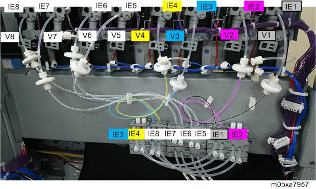
V: Solenoid Valve
IE: Ink End Detection

When installing, make sure to insert tubes and stoppers correctly.
When routing tubes, be careful not to bend the tubes or make scratches on the tubes.
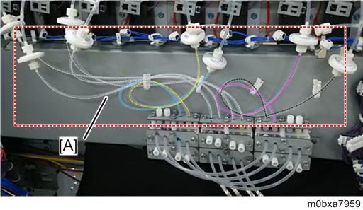
Remove the screws from the left upper cover [A].
- Front side, Top
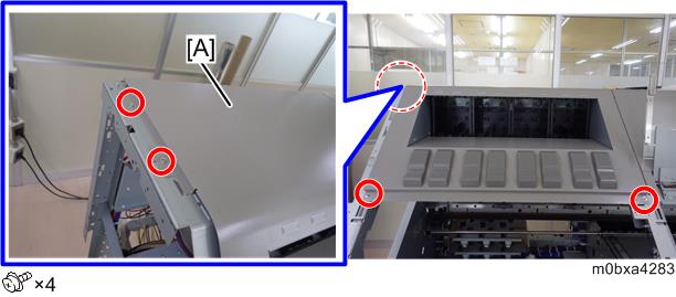
- Rear side
- Front side, Top
- Remove the left upper cover [A].
- Prepare the instruction sheet for changing the joints provided with the machine.
- Attach the sealing materials (MTLLP-2) [C] to the joint [B] branching from the T-shaped joint [A].
Connect the joint [D] of the tube extending from the solenoid valve [V2] and the joint [E] of the tube extending from the ink end detection [IE2].
The picture below shows the solenoid valve V1/V2.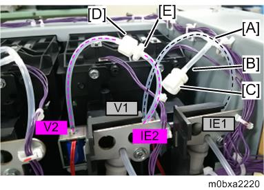
Connect tubes of the other solenoid valves (V3/V4, V5/V6, and V7/V8) in the same procedure.
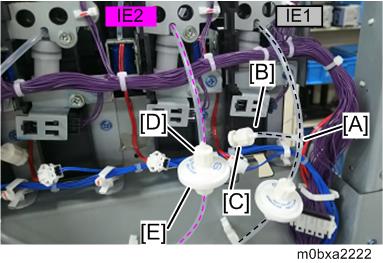
- Attach the sealing materials (FTLLP-1) [C] to the joint [B] branching from the T-shaped joint [A].
Connect the joint [D] of the tube extending from the ink end detection [IE2] and the joint of the filter upper side [E].
Connect tubes of the other ink end detections (IE3/IE4, IE5/IE6, and IE7/IE8) in the same procedure.
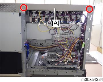
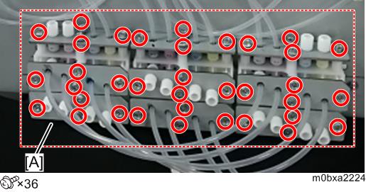
- Loosen all the screws retaining the joint branch unit [A] by rotating about from one to one and half times with a driver.
Connect the eight tubes for solenoid valve [A], the four tubes for joint section [B], the circulation tubes [13] - [16], and the 16 stoppers for joint section [C] as shown below.
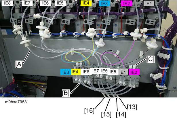
- The eight tubes for solenoid valve [A]
- The four tubes for joint section [B]
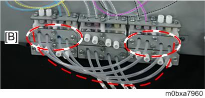
- The circulation tubes [13] - [16]
The tube number (No.13, 14, 15, 16) is written on each circulation tube. Connect the circulation tubes to the ports according to the number in the picture [B] above.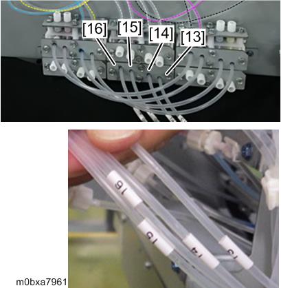
- The 16 stoppers for joint section [C]
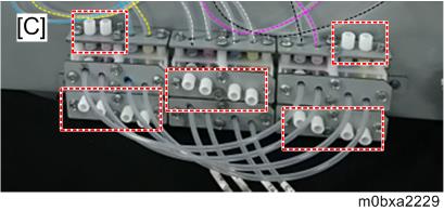
- The eight tubes for solenoid valve [A]
- Tighten all the loosen screws in step 6.
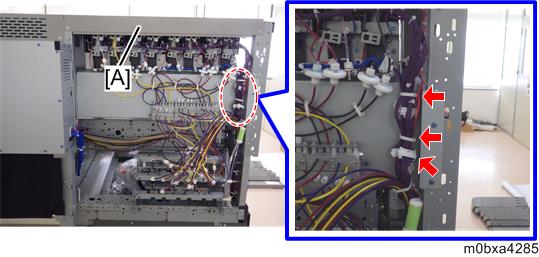
Fix the tubes.
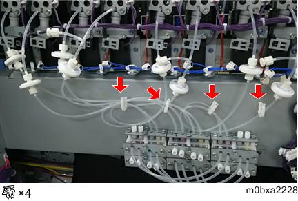
Be careful not to bend the tubes.
- Attach the left upper cover.
- Attach the rear left cover.