
If you adjust the machine in the power on state, insulate the driver for adjusting head position from the machine. Touching the driver to the circuit board of the damper sensor may blow fuses of the HDC and result in short.

If white ink is used, the Head Inclination and Sub Scan Deviation of Head 2 must be adjusted manually by checking the printed image according to "Manual Adjustment of the Head Position".
After replacing the print head unit, perform the necessary adjustments in the following order.
- Nozzle check
- Adjustment of Sub-scan Direction Feed Amount
- Measuring Head Inclination (Absolute)
- Measuring Head Inclination (Measuring Sub Scan Deviation)
- Drop Position Adjustment
- Make sure the following conditions are met.
Make the machine ready to print.
A coated paper or a glossy paper is recommended. (PVC also can be used.)
Set the heaters to 20 degrees, the cure heater to zero degree, and then turn off.When using cockling media cockled by heat like a coated paper or a glossy paper, set SP1-100-010 to 0, and then return the value to the original value after adjusting.
The media width must be 420 mm or wider.
Media skew affects the results of the adjustment. So we recommend the adjustment in the condition of roll to cut without setting the media to the roll-up section.
Cut the media frequently. If the machine is transported with the end of the paper touching the floor, transport skew or meanders may be caused.
Dots may move and combine on the impermeable media, which causes the wide range of the measured value. Using permeable media is recommended.
- Perform nozzle check (Nozzle Check Pattern Printing/Checking).
- Perform Adjustment of Sub-scan Direction Feed Amount (Adjustment of Sub-scan Direction Feed Amount).
Adjusting Head Inclination
- Execute head cleaning. (About Head Cleaning)
- Enter the SP mode, and then execute SP5-922-001 (Measuring Head Inclination Absolute).
Colorimetric sensor reads the inclination of the three heads.
If the error (read value is -5000) occurs, it can be caused by outputting the pattern exceeding the extent that the sensor can measure.
Adjust the tilt of the head manually so that the pattern is within the extent. The results are displayed in the following SP (Head Inclination Value).
SP3-175-004 (Head1 (Cal. by Skew/MainScan Deviation))
SP3-175-005 (Head2 (Cal. by Skew/MainScan Deviation))
SP3-175-006 (Head3 (Cal. by Skew/MainScan Deviation)) - Loosen the screws fixing the print heads.
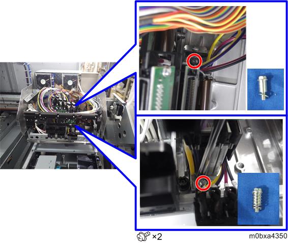
- Loosen the hex screws (2.5 mm) in the cams.
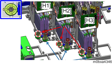
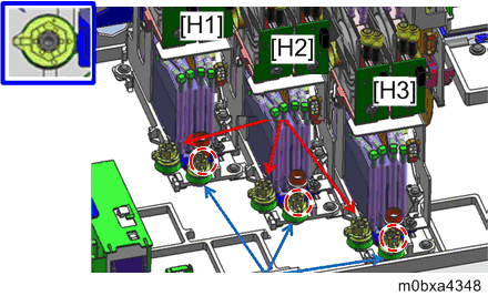
Rotate the adjustment cam [A] to adjust the head inclination.
Refer to the following table for the rotation angle of the cam.
Rotation angle (degree) Moving distance (  m)
m)10 4
20 8
30
12.1
40
16.2
50
20.4
60
24.8
70
29.3
80
34
90
38.9
100
44.3
110
50.2
120
57
130 65.3 140 78.1 144 90 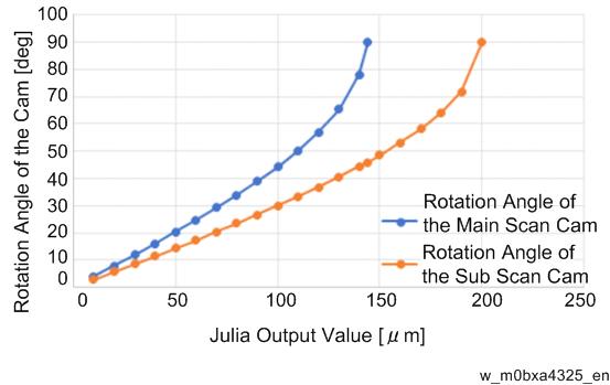
Adjust the head inclination so that the value displayed on the operation panel reaches ±10
m.- Tighten the screws loosened in step 3 and 4.
Adjusting Head Position in the Direction of Sub Scan
- Execute head cleaning. (About Head Cleaning)
- Execute SP5-922-003 (Measuring Head Inclination Measuring Sub Scan Deviation).
The results are displayed in the following SP (Head Sub Scan Displacement). SP3-175-010 (Measured Displacement Amount (Head1-Head2))
SP3-175-011 (Measured Displacement Amount (Head1-Head3)) - Loosen the screws fixing the print heads.
- Loosen the hex screws (2.5 mm) in the cams.
Adjust the head position until the value displayed on the operation panel turns ± 10
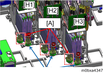
m. Rotate the sub scan direction head position adjustment cam [A] to adjust the head position.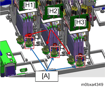
For the rotation angle of the cam, refer to the following table and the graph in the step 5, Adjusting Head Inclination.
Rotation angle (degree) Moving distance ( m)10 2.8 20 5.7 30 8.6 40 11.5 50 14.4 60 17.4 70 20.4 80 23.5 90 26.7 100 30 110 33.3 120 36.8 130 40.5 140 44.4 150 48.5 160 53.1 170 58.2 180 64.1 190 71.8 200 90 - Tighten the screws loosened in step 3 and 4.
Check the inclination again using SP3-175-004, 005, and 006.
*The colorimetric sensor has a repeatability error by about ± 10
m. If the value is once adjusted within± 10m, the value within ± 20m may appear on the display as a result of re-reading. Target value is ± 20m in the checking procedure.*If the displayed value appears strange, execute head cleaning, and then execute the print/scan process again.
Head Inclination Direction and the Sign of the Displayed Number
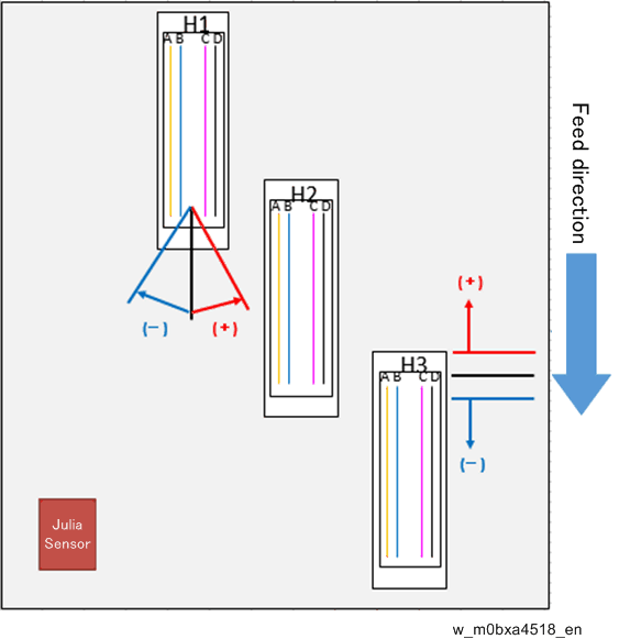
The Sign of Head Inclination
+: The print head is inclined to the right from the rotation center of the print head to the transportation direction axis line. (Counterclockwise)
-: The print head is inclined to the left from the rotation center of the print head to the transportation direction axis line. (Clockwise)
The Sign of Sub Scan Direction Head Movement
+: When the downstream print head is shifted to the direction closer to the upstream print head. (Overlapping between the two print heads is too big.)
-: When the downstream print head is shifted to the direction away from the upstream print head. (Overlapping between the two print heads is too small.)
Locations of the head inclination adjustment cams and the sub scan direction head position adjustment cams
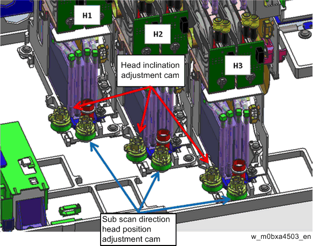
Head Moving Direction by Using Cam
For the rotation angle of the cam and moving distance, refer to the graph in the step 3, Adjusting Head Inclination, and also refer to the graph in the step 3, Adjusting Head Position in the Direction of Sub Scan.
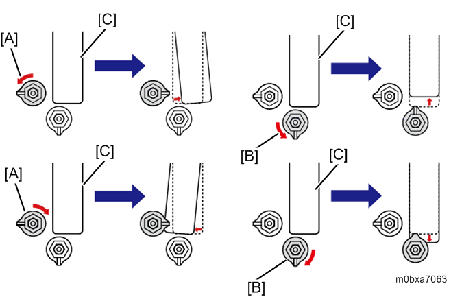
- [A], [B]: Cam
- [C]: Head