Component Layout
The capping unit has the following functions.
- Caps the print head during idle time to prevent the head surface from drying.
- Helps the machine to resolve head clogging by keeping the print head capped during ink suction operation.
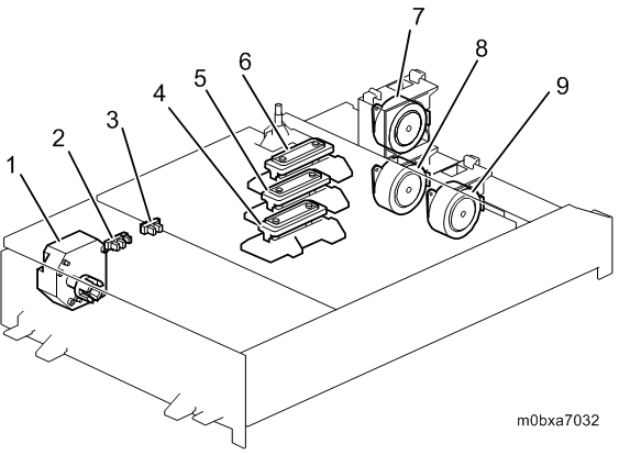
| No. | Name | No. | Name |
|---|---|---|---|
| 1 | Maintenance Unit Lift Motor | 6 | Cap (Head 1) |
| 2 | Maintenance Suction Unit Decap Sensor | 7 | Maintenance Unit Ink Collection Motor 2 |
| 3 | Maintenance Suction Unit HP Sensor | 8 | Maintenance Unit Ink Collection Motor 1 |
| 4 | Cap (Head 3) | 9 | Maintenance Unit Ink Collection Motor 3 |
| 5 | Cap (Head 2) |
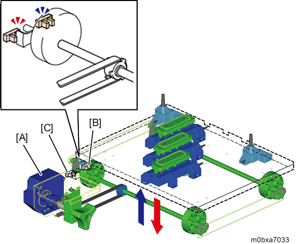
Capping Unit Lift Mechanism
The capping unit keeps the humidity of the print head by capping/decapping the print head through moving down when printing starts and moving up during idle time.
The maintenance unit lift motor [A] moves up/down the capping unit. The maintenance unit lift motor [A] rotates the shaft at the bottom of the capping unit and the cam on the shaft lifts the unit. The maintenance suction unit HP sensor [B] detects capping state and the maintenance suction unit decap sensor detects decapping state.
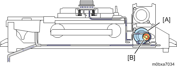
Ink Suction Mechanism
Through suction with the head capped, the machine resolves print head clogging and generates negative pressure which prevents ink dripping.
When the cap moves up and caps the head, the maintenance unit ink collection motor [A] drives the pump unit [B] which sucks the ink. The waste ink is collected in the waste ink bottle through the tube.