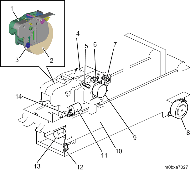
Component Layout
The wiping unit is equipped with the cleaning cartridge. The cleaning cartridge consists of the wiper blade and the web and cleans the head surface during head cleaning.
The wiper blade rubs the head surface to remove ink and paper dust. When head cleaning is over, the web cleans the objects on the wiper blade. The flushing cartridge drips cleaning liquid on the web. The web wipes the nozzles before wiping.
| No. | Name | No. | Name |
|---|---|---|---|
| 1 | Cleaning Cartridge | 8 | Maintenance Unit Web Shift Motor |
| 2 | Web | 9 | Maintenance Unit Wiper Motor |
| 3 | Web Roll-up Roller | 10 | Wiping Unit |
| 4 | Wiper Blade | 11 | Maintenance Unit Web Adjust Motor |
| 5 | Maintenance Unit Web Encoder Sensor | 12 | Web Front/Rear HP Sensor |
| 6 | Blade Wiper HP Sensor | 13 | Maintenance Unit Web Supply Motor |
| 7 | Web Up/Down HP Sensor | 14 | Maintenance Unit Web Adjust Sensor 2 |
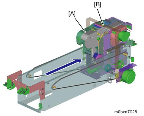
Print Head Cleaning
Driven by the maintenance unit web shift motor, the wiping unit moves in the sub scan direction. The web and the wiper blade scratches off objects on the surface of the head. The cleaning operation proceeds as follows:
- 1. Dripping the cleaning liquid
- The wiping unit [A] moves to the position where cleaning liquid can be dripped (the back position).
- Cleaning liquid is dripped onto the web [B].
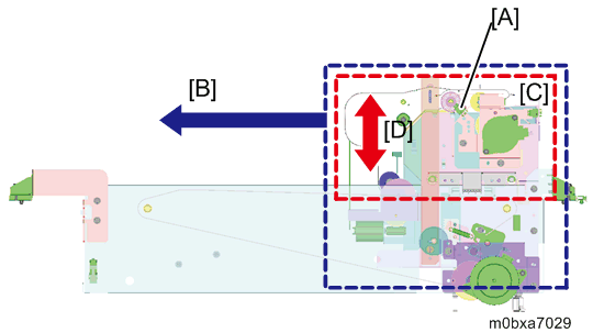
- 2. Wiping
The wiping unit [A] moves ([B]) to the wiping start position.
The carriage unit moves in the main scan direction to the wiping position.
The nozzle cleaning cartridge [C] moves up ([D]) to the wiping height.
The wiping unit moves ([B]) in the sub scan direction (from back to front) and starts wiping.
Just before wiping starts, the web onto which the cleaning liquid was dripped absorbs and collects ink on the head nozzle surface.The nozzle cleaning cartridge [C] moves down ([D]).
The wiping unit moves ([B]) to the home position (the front position).
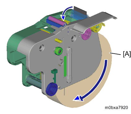
- 3. Web Wiping
- The web [A] rubs the nozzle surface of the print head.
The web [A] is rolled up a predetermined amount.
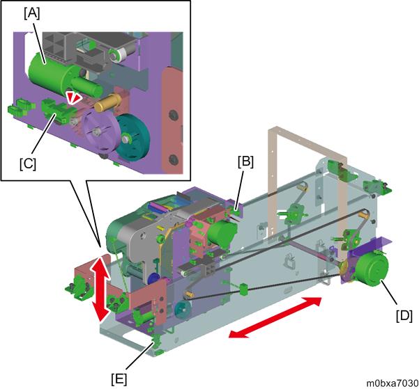
Web Cartridge Lift/Wiping Unit Shift Mechanism
- Web Cartridge Lift Mechanism
During wiping, the maintenance unit web adjust motor [A] moves up/down the web cartridge. Home position is detected by the web up/down HP sensor [B]. The maintenance unit web adjust sensor 2 [C] monitors the encoder to control the up/down movement. - Wiping Unit Shift Mechanism
During wiping, the maintenance unit web shift motor [D] shifts the wiping unit forward/backward via the timing belt. Home position is detected by the web front/rear HP sensor [E].
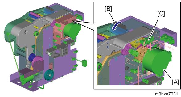
Blade Cleaning
The maintenance unit wiper motor [A] performs blade cleaning by rotating the wiper blade [B] until it comes into contact with the web. The home position of the wiper blade is detected by the blade wiper HP sensor [C].
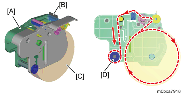
Cleaning Cartridge
The cleaning cartridge [A] has the wiper blade [B] and the web [C]. After web wiping, the maintenance unit web supply motor drives the web roll-up roller [D] to roll up used web. This renews the contact surface of the web.
An ID chip is attached on the side of the cleaning cartridge. The ID chip stores information including new/used detection, lot number and amount of remaining web.
Set detection of the cleaning cartridge is done when the cleaning cartridge set sensor detects the ID chip.
Web Near End/Web End
Web consumption is counted by the Maintenance Unit Web Encoder Sensor.
Web near end
The machine displays web near end on the operation panel when the remaining web is below the threshold configured in SP2-254-001.SP No. Name Default Range SP2-254-001 Web Near End Threshold: Residual Qty. Ratio 20% 0 - 80 % Web end
When the remaining web is below the threshold configured in SP2-255-001 and web roll-up is stopped, the machine detects web end. After web end is detected, the machine stops printing. "Web end" is written in the ID chip of the web cartridge and the cartridge can no longer be used.SP No. Name Default Range SP2-255-001 Web End Detection Threshold: Residual Qty. Ratio 2% 0 - 80 %